A simple "discrete" DDS VFO for 136kHz.
By Pavel Vachal, OK1DX.
G3YXM's notes:
This DDS uses 74HC series CMOS chips to generate 256 discrete frequencies between 135.68 and 138.23 kHz in 10Hz steps. Because the chips are cheap and easily available the cost of this project is low, about £20.
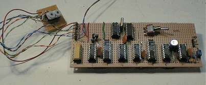
I built the version pictured in a day using wirewrap and it worked first time. The only problems I had were getting the crystal oscillator to start reliably and VCO adjustment.
The crystal oscillator (U7D and U7C) works at 6.5536MHz and is divided down by U8A to either 1.31MHz, for 272kHz output or 655KHz for a 136kHz output. The choice is made by links JP1 and 2. This clock feeds the binary adders and registers which are programmed by the hex switches connected to J2.
A 4046 VCO locks to the "raw" dds ouput and produces a spectrally pure output.
My breadboard version, the Hex switches on the left select the frequency. The toggle switch is the 136 / 272 kHz switch.
The full circuit diagram.
Notes:
The Hex switches are connected to J2 as follows: pin 1=common of both switches (+5V) 2=LSB up to 5=MSB of first switch. Then 6=LSB of second switch up to 9 which is MSB.
On the output connector J1. Pin 1 is the raw DDS output, not very spectrally pure. Pin 2 is the clean VCO output (5V square-wave) and pin 3 is ground.
The VCO values given are for 272kHz use, if you want to run the DDS directly on 136 you will have to alter C13.
I modified the oscillator slightly to get my cheap Farnell crystal to start reliably (Philips 74HC00 chip). Increase R2 to 1 Meg-Ohm add another C of about 200pF from pins 9,10,11 to earth.
Ensure you decouple the VCO (4046) chip properly and choose a 5V regulator with a slightly high output (it MUST be fed from a regulated supply), it didn't seem to like 4.9V! The other chips will stand up to 6V.
You will need a buffer stage to level-shift up to 12V if you want to drive the G3YXM TX with it. I used a single common-emitter NPN stage; 10k from input to base, 4k7 from base to ground, 1k from collector to 12V, emitter grounded. The output comes from the collector. This isn't great but it will drive down a metre of coax!
Mods.
I am currently playing with a "VFO knob" interface using binary counters. When I get it going I'll publish it here.
Pavel has an idea to implement this system in a PIC chip which will make a simple one-chip DDS. Maybe even with a frequency readout!
Many thanks to Pavel Vachel OK1DX. This design is his copyright.
Download the diagram (right mouse-click and "save target as..")