ROPEX "THE FIRST" 136kHz TRANSMITTER
Use of the 136kHz band has been rising steadily over the last year and many stations are now active. Many more would like to get on the band, but do not have the time and/or inclination to home-brew a transmitter. The introduction of the first off-the-shelf transmitter for 136 should enable them to get started.
The fact that a commercial TX is readily available doesn’t solve all the problems though, at present there is no LF ATU, SWR meter or aerial available and these will have to be constructed before any useful signal will be radiated! Some tips on getting started are included at the end of this review.
DESCRIPTION
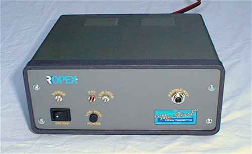
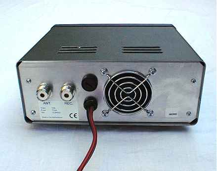
Ropex’s "the First" is a compact rig measuring 200mm wide x 90mm high x 175mm deep with a clamshell type metal case finished in olive green, having an internal frame upon which the major components are mounted. The front panel has only an on/off switch, a low/high tx power switch and a key socket to play with, plus some indicator lights. The rear panel is even sparser with only an aerial socket, a receiver socket, a fuse and the captive power lead. Simplictity is definitely a watchword here.
Delving inside reveals a well laid-out double-sided PCB onto which all the components are mounted. The output mosfets are clamped to an L shaped heatsink which is in the full draught from a small computer type fan mounted on the rear panel.
I was disappointed to see that the manufacturers had filed the type number off the driver chip making identification difficult, there’s no circuit provided so what do we do if it fails? Other worries were the fact that the large toroidal output transformer is supported merely by its wires - a long bumpy trip in the back of a car may cause some of the connections to fracture - also there was no earth strap to the back panel where the aerial socket is mounted, so the RF current has to flow all round the case to get there - keep the screws tight!
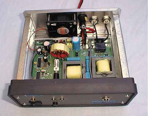
The neat internal construction of the Ropex revealed. The red output transformer can be seen near the back. The two large cores at the front right are the output filter inductors. You can just see the fixed crystal between the two ICs on the left.
TESTING
First I tested the rig into a dummy load. I connected the red and black cable to a suitable 12V 20A PSU (it’s a bit short so you’ll need to add a length via the supplied choc-block), connected a 50 Ohm dummy-load, connected a key and pressed! "The First" has a "VOX" type circuit and so goes onto tx automatically the first time you press the key, after a delay of about 1 second it drops back to receive. This seemed fine for the sort of speeds I use but may prove a bit long if you are going at 20wpm or so!
On a 12V supply and with the low/high button out, the rig drew around 3.5A and produced about 25W of RF, with the button in it rose to 15.8A and 136W. Using 13.8V the current rose to 17.5A and the output to 172W into 50 Ohms. This equates to a total efficiency of about 72%. This good efficiency is typical of a class D switching design.
The current in standby is about 250mA.
Checking the harmonic output revealed the expected lack of even harmonics from the square-wave PA and well suppressed odd harmonics. The third harmonic, which falls amongst the aeronautical beacons, was more than 35dB down which is very good for this kind of PA. It must be remembered that any 136kHz ATU will be very sharp and should remove the last vestiges of any harmonic energy.
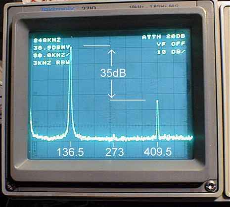
Here we can see the fundamental and the second and third harmonics. The third harmonic is well suppressed at –35dB.
So far so good! The next step was to connect the tx to my aerial. I had checked that the SWR on 136.5 was OK before connecting the Ropex and so was most surprised to find that I couldn’t use the high power setting. The tx worked fine at low power producing about 30W but as soon as I switched to high power (button in, green light on) it produced a few Watts and drew hardly any current. My ATU has a tap a few turns up from the earthy-end of the coil where the 50 Ohm point is found. It seems that for some reason the protection circuit of "the First" does not like this arrangement. Reconfiguring the ATU as a simple series coil, although giving a slightly worse match, seemed to cure the problem. I later found that a 50 Ohm to 50 Ohm pi network between the tx and the ATU cured the problem and so was able to return my ATU to its normal state and continue with the tests. I have reproduced the circuit of the the pi network here as I regard the tapped coil as the best way of setting up an LF aerial, especially with kite aerials where the DC path to earth is essential to dissipate static.
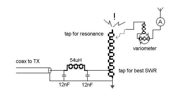
Circuit of the test ATU. The main coil has 150 turns of 1.5mm o.d. plastic covered wire on a perspex cage former 200mm diameter. The 54uH inductor is 65 turns of 1mm wire on a T130-2 dust-iron core. The 12nF capacitors are made up from 10nF and 2n2 1000V "pulse" rated poly Cs.
Quite why the protection circuit reacts in this way I was unable to determine. It appears to sense the RF current at the output of the low pass filter in the tx and shut off the drive when the level gets too high. In normal use this equates to about 20A of DC input current.
ON THE AIR
Once the ATU was tamed I put out a few CQ calls, there is no side-tone so you have to listen to the transmitter on the receiver. This is not a problem if the station you are working is co channel but if they’re at the other end of the band you won’t hear anything when you key. Reports were good for the limited power and I liked the "VOX" facility. I was a little concerned about the hard keying shape, fearing that locals may notice some clicks, but my nearest local at 25 miles away was quite happy with the sound of the signal. Keying via the computer (for very slow CW) also worked well. The open-circuit voltage on the key socket is only 8V and the key-down current is about 12mA so it’s easy to drive with an opto-coupler or similar device.
Although the spec states that the tx frequency is 136.5kHz it is actually 136.54, being a crystal oscillator at 6.554Mhz divided by 48. If a number of operators buy these rigs this will become a rather congested frequency! It is therefore annoying to find that the crystal is difficult to remove being soldered into the board with its case soldered down to the earth plane. If a socket had been fitted, crystal changing would have been easier and a VFO or synthesiser could have been plugged in. Perhaps "the Second" will incorporate this feature! Whilst I’m grumbling, the instruction leaflet provided is not exactly comprehensive. It consists of one sheet of paper with a very abbreviated set of directions and, as previously mentioned, no circuits. I have therefore included a little more information on tuning up.
GETTING TUNED UP.
A simple tapped coil is the usual ATU for LF. The likely length of aerial wire in use will be a tiny fraction of a quarter wave and will appear as a high impedance with capacitive reactance, just like a short whip on topband. The number of turns required will depend on what diameter of former you happen to have and what length of wire you are attempting to tune up.
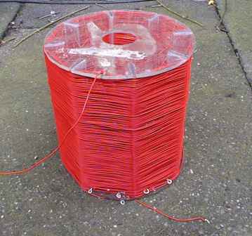
The test loading coil as described. It has an inductance of about 3mH.
About 3mH is a good start with taps every ten turns or so near the top of the coil and every turn for the first 6 turns at the bottom. You will notice that no tuning C is used, one could be used but it would have to be a very wide-spaced one, the impedance is so high that 10kV of RF is possible with the comparatively low output of the Ropex.
Most aerial systems alter in resonance with the weather, wet days it’ll go LF and dry ones it’ll go HF, therefore you are going to need some way of making fine adjustments. If you don’t have an old broadcast transmitter vacuum variable C available then the best bet is a home-brew variometer.
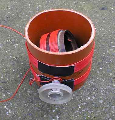
Home made variometer using sticky-tape and ball-pen technology ( I used an old pen body for the shaft.)
The variometer pictured is made from a piece of 4" diameter plastic pipe ("stench pipe" as I heard it charmingly called…) with another, 3" dia coil able to rotate inside it. The inner coil is wired in series with the outer one and, as it is rotated, it either adds to or subtracts from the total inductance. Mine has a range of 60 to 140uH, more than enough to keep the aerial on resonance in most conditions. Don’t use any metal parts (except the wire of course!) in the construction or they will arc, plastic is best and ensure that you can adjust the thing without getting your fingers too close to the wire, RF burns hurt!
To get the atu somewhere near, tune to the German data transmission on about 138.8kHz (a carrier with an occasional data burst) and set the atu taps for the loudest signal with the variometer in the centre of its travel (inner coil at 90° ). If all is well the tuning will be quite sharp and the signal should be S9+.
Start with the low-power setting on the tx and key up. If you have an aerial current meter, a small peak should coincide with a dip in reflected power. Optimise the SWR with the earthy-end taps (you will need the pi-network in cct if your tx reacts the same way as mine). The tx should be drawing just under 4A. When you are happy with that, switch to high power (Ropex warn not to operate the power switch with the key pressed) and try again. If there are no flash-overs and the SWR stays good then the tx should be drawing just under 15A, a slight tweak on the variometer should get this right.
Many HF SWR bridges will give a useful indication of SWR although the actual power readings will be low. My old Daiwa 620 reads 8W when the Ropex is producing its 140 Watts.
CONCLUSION
The "First" is a useful little transmitter, neatly made, very efficient and with some nice features but it has its limitations. The complete lack of any monitoring built into the rig means extra bits and pieces need to be bought or constructed before it can be operated satisfactorily. If I were keeping it I would reduce the speed of the fan a little. Although the noise it makes is not offensive, just a rushing sound with no distracting note, it is quite loud. Having had a couple of long QSOs I could detect no heating of anything in the rig so there is certainly no lack of cooling!
It must also be noted that 130W or so is not an awful lot of power with which to radiate a signal on the 136kHz band, a good aerial is going to be required to work DX.
The biggest drawback, however, is the fixed frequency. I appreciate that the addition of a VXO or VFO would have increased the price considerably but the difficulty of changing the crystal is a great shame. A mark two with a switch and an external crystal socket would be my suggestion.
If you want to get going on 136 and can live with the shortcomings give a Ropex a try, I think it’s good value and as well as being "the First" it’s also the Only!
The Ropex "the First" is available from Nevada 01705 662 145
Dave Pick G3YXM
Published in "Radio Today" magazine in June 1999.